Coil Dimension Guidelines
Dimension Guidelines for HVAC/R Coil Design
The list of coil dimensions below is a guide for customers in need of design-build, replacement, and OEM coils, detailing the available dimensions for fins, rows, side plates, casings, and connections for various coil types. Precision Coils’ staff are always available to guide customers through the process of obtaining and calculating coil dimensions to ensure our expertly engineered coils perfectly fit your HVAC/R system.
Rows
- Chilled Water and DX Coils: 1–12 rows
- Hot Water Coils: 1–12 rows
- Steam Coils: 1–2 rows
- Condenser Coils: 1–12 rows
- Booster Coils: 1–12 rows
FPI – Fins Per Inch
- 1/2″ outer diameter (OD) tube coils: 6–16 fins per inch
- 3/8″ OD tube coils: 10–20 fins per inch
- 5/8″ OD tube coils: 6–14 fins per inch
- Standard fins are .006″ die formed aluminum with collared tube holes
- Optional fins are .008″ and .010″ aluminum and .006″ copper
- Contact factory for special fin materials and fin coatings
FH – Fin Height
Fin heights are dictated by our tube patterns:
- For 5/8″ tube coils, fin heights are available in increments of 1-1/2″
- For 1/2″ tube coils, fin heights are available in increments of 1-1/4″
- For 3/8″ tube coils fins are available in 1.00″ increments
FL – Fin Length
Maximum fin length is 250″. Center supports (also called tube supports) are required for every 50″ of fin length. A center support is sheet metal with tube holes used to support the middle of the fin pack.
SP1, SP2 – Sideplate Flanges
- Standard flanges are typically 1-1/2″ and stackable. Minimum stackable flange is 1/2″.
- Inverted, flat sideplate flanges are typically 1″ and Casing Height (CH) is increased on both sides by the 1/16″ thickness of the metal (e.g. 9″ Fin Height + Inverted Flat Side Plates = 9-1/8″ Casing Height).
- Available casing materials are 16-gauge galvanized steel, 16-gauge stainless steel, .06″ or .09″ copper.
EP1, EP2 – End Plates
(Also Called Tube Sheets)
- Standard flanges are usually 1-1/2″ and made of 16-gauge galvanized steel.
- 16-gauge stainless steel end plates are also available.
CH – Casing Height
- For coils with stackable flanges, casing height is calculated as follows:
CH = SP1 + FH + SP2
(e.g. SP1 = 1.5, FL = 30, SP2 = 1.5)
CH = 33 - For inverted flat casing, casing height is calculated as CH = FH + 1/8
CL – Casing Length
CL = EP1 + FL + EP2
CD – Casing Depth
Standard coil casing depths are as follows:
| Rows Deep | “CD” Dim |
|---|---|
| 1 | 5 |
| 2 | 6-1/2 |
| 3 | 6-1/2 |
| 4 | 7-1/2 |
| 5 | 7-1/2 |
| 6 | 10 |
| 8 | 12 |
| 10 | 15 |
NOTE: These dimensions were chosen to ensure that headers remain inside the casing, but modifications can be made as long as:
- CD > Fin Pack
- Where CD is Casing Depth
- Fin pack = (No. Rows) * (Centerline Distance Between Rows)
Max
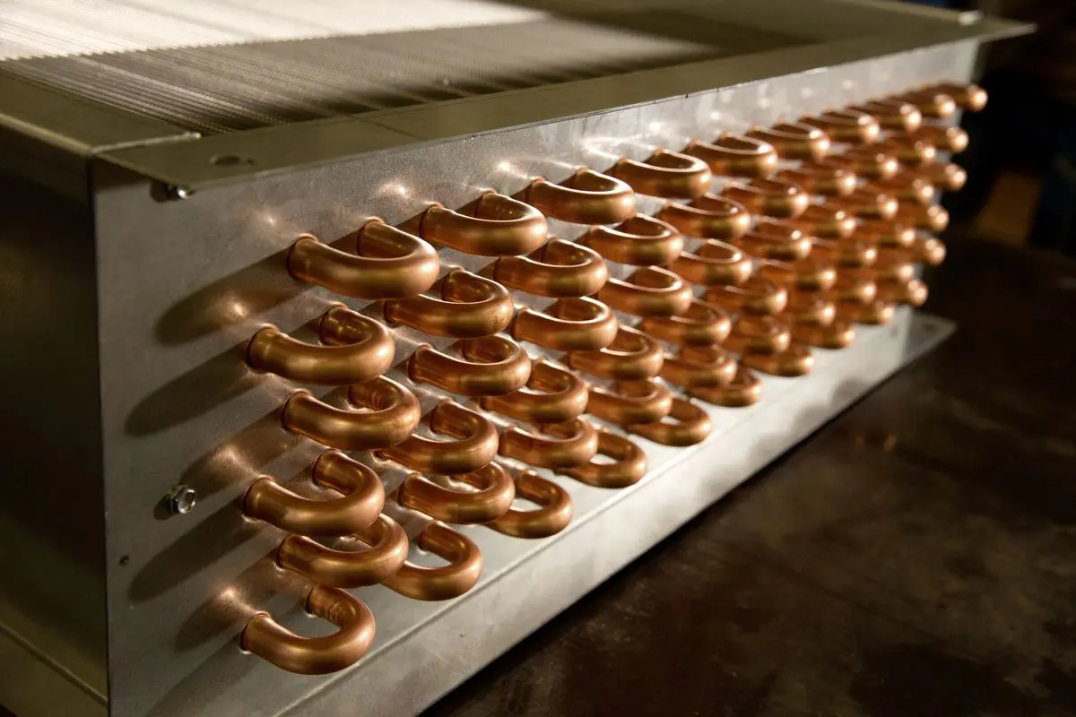
- MAX is the dimension from the edge of the fin pack to the outside of the return bend. A return bend is simply a bent copper tube connecting two adjacent rows.
- Minimum MAX dimension is 1-1/2”.
- Typical MAX dimension is 2-1/4”.
Sometimes the flange, EP1, exceeds the MAX dimension. In these cases, substitute the MAX dimension with EP1.
“C” Dimension
- “C” is the dimension from the edge of the fin pack to the outside of the header. For opposite end connection coils, there would be two “C” dimensions – C1 and C2. Attached to the header are copper tubes or “adapter” tubes which connect the coil tubes to the header.
- Standard adapter tube lengths are 3-1/8” and 1-7/8”.
Example: Coil has a 1-1/8” header with 3-1/8” adapter tubes
C = 1-1/8 + 3-1/8 = 4-3/8
NOTE: All double circuit coils to have a minimum adapter tube length of 3-1/8”.
OAL – Overall Length
- For same-end connection coils, overall length is the dimension from the edge of the return bends on one end to the outside of the header on the other end.
OAL = MAX + FL + C
Example: MAX = 2-1/4 + FL = 48 + C = 4-3/8; OAL = 54-5/8
- For opposite end connection coils, overall length is measured from the outside of the header on one end to the outside of the header on the opposite end.
- OAL = C1 + FL + C2
Example: C1 = 3-1/8 + FL = 48 + C2 = 3-1/8; OAL = 54-1/4 - Note that connection length “L” is not included in the “OAL” dimension.
L-Connection Length
- Coil connections are typically copper or steel. Copper connections can be made any length down to a certain minimum.
- Steel connections have fixed lengths as shown in the chart below.
- Standard connection types for various Precision Coils:
- Water and Steam Coils: Copper male pipe thread (MPT) connections (with options for copper female pipe thread (FPT) or Steel MPT connections).
- DX Coils: Supply connections are brass distributors with a removable-type orifice and an optional side port connection for hot gas bypass. Suction headers have Copper SWEAT connections.
- Condenser & Heat Reclaim Coils: Copper SWEAT connections.
Typical Connection Lengths for Standard OD Connection Sizes
| Conn Dia. | STD MPT “L” Dim. | STD FPT “L” Dim. | Absolute Minimum “L” Dim. |
|---|---|---|---|
| 3/4 | 2 | 2 | 1-1/4 |
| 1 | 2 | 2-1/4 | 1-1/4 |
| 1-1/4 | 3 | 2-1/2 | 1-1/4 |
| 1-1/2 | 3-1/4 | 2-1/2 | 1-5/8 |
| 2 | 3-1/2 | 3 | 1-3/4 |
| 2-1/2 | 3-1/2 | 3-1/4 | 2 |
| 3 | 4 | 3-1/4 | 2 |
Connection Sizes – Header Diameters
- As shown in the chart, standard MPT and FPT connection diameters (ODs) range from 3/4” to 3”. Contact the factory for special connection sizes.
- For water coils, connection sizes are typically sized based on gallons per minute (GPM) of water.
- For SWEAT connections and header diameters, add 1/8” to the standard connection size.
| GPM | Connection |
|---|---|
| 1-4 | 3/4 |
| 4-8 | 1 |
| 8-16 | 1-1/4 |
| 16-30 | 1-1/2 |
| 30-40 | 2 |
| 40-75 | 2-1/2 |
| 75-100 | 3 |
Header OD = Connection Size + 1/8”
Sweat Connection = Connection Size + 1/8”
(e.g. Coil with 1” MPT connections, header OD = 1-1/8”)
Exceptions: Non-Freeze Steam Distributing coils have fixed header diameters regardless of connection size.
1 Row Steam Dist. Coil = 2-5/8” OD Header, unless supply is 3″ then header is 3-1/8″.
2 Row Steam Dist. Coil = 3-1/8” OD Header
“S” and “R” – Connection Locations
Connection locations may vary according to whether you are replacing an existing coil or designing a new coil. For Precision Coils, standard connection locations “S” and “R” are determined from the centerline of the connection relative to the top and bottom of the casing.
For Water Coils, Standard Steam, Direct Expansion, and Condenser Coils:
- S or R = 1/2 (Conn size OD) + .5
(e.g. Conn Size = 2, S = 1.5)
For Steam Distribution Coils:
- S + 1/2 (Casing Height)
R + 1/2 (Conn Size OD) .5
“E” and “F” – Connection Locations
“E” and “F” dimensions are determined from the centerline of the connection relative to the sides of the casing. These dimensions are probably the most “mysterious” of all coil dimensions, for they are dependent on many factors – number of rows, tube pattern, header diameter, type of offset adapters available, etc. The following schematic and respective formulas should help in calculating “E” and “F”.
X = (No. Rows – 1) * (Distance between rows)
- For 5/8” tube coils: Distance between rows = 1.30
- For 1/2” and 3/8” tube coils: Distance between rows = 1.08
- For 1 row coils: “E” and “F” = 1/2 (CD) +/- (Offset Option)
- For 2 – 12 row coils: “E” and “F” = 1/2 (CD – X+ +/- (Offset Option)
Note: Offset Option – Offset adapters are required if the header diameter is greater than the dimension “X”.
Standard offsets for Precision Coils
- 5/8” tube: 0.75, 1.30, 2.05, 2.60
- 1/2” tube: 1.08, 2.16
NOTE: All standard offset adapters are 3-1/8” long
Precision Coils can provide special offset adapters if required. For special offsets contact the factory.

Right Fit. Right Now.