Installation & Maintenance
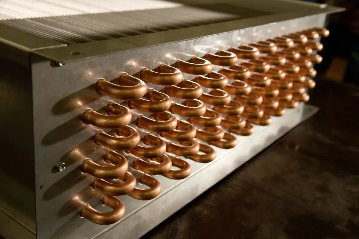
Water Coil
Installation Recommendations
- Provide separate supports and hangers for the coil and for the piping. Piping should be in accordance with accepted industry standards (reference ANSI/MSS SP-58-201 and the International Mechanical Code). Always use a backup wrench on the coil connections when attaching the piping to the coil if pipe thread connections are utilized.
- For drainable coils, tubes should be installed horizontally using a spirit level. If the tubes cannot be installed level, special drain headers are available on request.
- Connect the water supply to the bottom connection on the air-leaving side and the water return to the top connection on the air-entering side.
- When four connections are provided, the extra bottom connection can be used for an auxiliary manual drain connection, and the extra top connection can be used for an automatic air vent. The extra connections can also be capped. Connecting the supply and/or return in any other manner will result in very poor performance.
- Water coils are not normally recommended for use with entering air temperatures below 40°F. Glycol solutions or brines are the only freeze-safe media for operation of water coils for conditions with low-temperature entering air.
- When fresh and return air are to be heated or cooled by a water coil, care should be used in the design of the ductwork to ensure thorough mixing before the air enters the coil. The return air should always enter the bottom of the duct. Fresh air should enter the top of the duct. The greater the distance between the points of mixing and entrance to the coil, the better the application.
- Two position control valves, modulating valves, three-way valves or a combination of these controls can provide control of water coils. Follow the recommendations of the control manufacturer regarding types, sizing, and locations. Face and bypass dampers may also be used, but do not close off tightly. Air leakage in cooling applications has no appreciable effect. In heating applications, however, the air temperature may rise several degrees and should be considered in system design. Low leakage dampers may be required.
- Pipe sizes for the system must be selected based on the head (pressure) available from the circulating pump. It is recommended that the velocity should not generally exceed 8-ft. per second, and that the friction loss should be approximately 3-ft. per 100-ft. of pipe.
- When cooling coils are banked two or three high, an intermediate drain pan with plastic drain tubes extending into the main drain pan should be installed on the air-leaving side of each coil. On high latent installations, the condensate draining from top coils may load the lower coils with condensate, resulting in reduced air flow and performance. Condensate could also be blown downstream into the ductwork. All individually installed water cooling coils, and the bottom of all cooling coil banks, should be mounted in drain pans extending at least 10” from the leaving-air edge of the coil. A drain line trap must be installed to allow condensate to drain freely. The drain line trap depth must be twice the negative static pressure of the operating system for the unit to drain correctly. Incorrect trapping can cause the drain pan to overflow.
NOTE: Vent and drain connections are provided on Precision Coils water coils unless otherwise specified. This allows the coils to be drained. Keep in mind that when draining the coils, all water may not drain from the coil. To completely drain the coil and prevent the possibility of freezing during cold ambient temperatures, air or nitrogen pressure must be utilized to blow any remaining water from the coil.
Steam Coil
Installation Recommendations
- General
- Provide separate supports and hangers for the coil and for the piping. Piping should be in accordance with accepted industry standards (reference ANSI/MSS SP-58-201 and the International Mechanical Code). Always use a backup wrench on coil connections when attaching piping to the coil. Coils not designed with pitched casing or fin pack must be pitched 1/4″ per foot towards the return connection at installation.
- Be certain that adequate piping flexibility is provided. Stresses resulting from expansion of closely coupled piping and coil arrangement can cause serious damage.
- Do not reduce pipe size at the coil return connection. Carry the return connection size through the dirt pocket, making the reduction at the branch leading to the trap.
- Vacuum breakers and air vents must be installed on all applications to prevent retaining condensate or air in the coil. Generally, the vacuum breaker is connected between the coil inlet and the trap. For a system with a flooded return main, the vacuum breaker should be open to the atmosphere, and the trap design should allow venting of large quantities of air.
- Do not drip steam mains through coils.
- Ensure the steam pressure and condensate line pressure differential is sufficient to allow efficient condensate removal from the steam coil, especially when using modulating steam control valves to control the leaving air temperature of the coil.
- Do not attempt to lift condensate without the assistance of a condensate pump. The pressure required to lift condensate must also be considered for sufficient pressure differential. Check valves are also required to prevent reverse flow of condensate back into the coil.
- To prevent freezing, entering air temperatures should not be below 40°F.
- Traps
- Size traps in accordance with the manufacturer’s recommendations. Be certain that the required pressure differential will always be available. Do not undersize.
- Float and thermostatic traps are recommended for high- or low-pressure steam systems, but bucket traps may be used. Float and thermostatic traps should be used when air venting is necessary. Bucket traps are only recommended for use with an on-off control. We recommend traps be located at least 12” below the coil return connection. When traps without air venting capabilities are used, air vents are required in the system.
- Multiple coil installations:
- Each coil or group of coils that is individually controlled must be individually trapped.
- For coils in series, separate traps are required for each coil, or bank of coils, in series.
- For coils in parallel, a single trap may be used but an individual trap for each coil is preferred.
- Control
- With coils arranged for series airflow, a separate control is required on each bank, or coil, in the direction of airflow.
- For high-pressure installations, a two-position steam valve with a face and bypass arrangement is preferred where modulating control is required.
- Modulating valves must be sized properly—DO NOT OVERSIZE.
Refrigerant Coil
Installation Recommendations
Refrigeration coils manufactured by Precision Coils are shipped with a small nitrogen holding charge. Care should be taken when opening these coils for installation. DX coil distributors have caps installed with soft silver solder. Once the cap is removed and if the thermal extension valve (TEV) is to be installed using anything other than soft solder, the distributor connection should be sufficiently cleaned with emery cloth to remove the soft solder. Follow accepted refrigeration piping practices and safety precautions per Ashrae Standards. If bends or right angles are necessary, long radius fittings must be used to keep the pressure drop through the piping at a minimum. Nitrogen charged and capped piping is recommended. Precision Coils’ general recommendations for component selection and line sizing are below.
Liquid Line Sizing
All compressors have a maximum Refrigerant Charge Limit (RCL) that must not be exceeded. Since the RCL and pressure drop are in direct conflict with each other, Precision Coils recommends the liquid line be sized as small as possible, while maintaining a low enough pressure drop to ensure 5°F of sub-cooling at the expansion valve.Liquid Line Components
Precision Coils recommends the use of a properly sized liquid line filter-drier installed upstream from the expansion valve as close to the evaporator coil as possible. Filter-drier selection should be based on a maximum pressure drop of 2 PSI at the design condition.A moisture indicator/sight glass should be installed between the expansion valve and filter-drier. The moisture indicator/sight glass must be sized to match the size of the liquid line at the TEV.
A liquid line shut-off valve with an access port should be sized with the selected liquid line outer diameter (OD) and installed close to the condenser.
The use of other valves, tube bends, and reducers should be minimized, since these items tend to increase pressure drop and reduce sub-cooling at the expansion valve. Liquid line receivers, other than those factory-installed, are not recommended.
The TEV must be selected for proper size, capacity, and the refrigerant being used. A slightly oversized valve will allow the unit to operate satisfactorily at low-load conditions. An undersized valve should not be used at any time, as this will starve the evaporator of refrigerant and cause insufficient air temperatures. The use of a hot gas bypass valve should also be considered when sizing the TEV. Select expansion valves with external equalizer connections, and those designed to operate against a backpressure of 20 PSI higher than the actual evaporator pressure.
The TEV must be installed directly on the provided evaporator coil liquid line connection. The liquid distributor must be installed vertically. If necessary, ensure that the distributor nozzle is installed in the distributor and that the installed nozzle is compatible with the refrigerant. Sensing bulbs must be mounted on a clean horizontal suction line close to the evaporator outlet and insulated properly. The bulb must be tight against the suction line at a 10 or 2 o’clock position, taking care not to overtighten and damage to the sensing bulb. The bulb should not be mounted directly on top or bottom of the suction line.
CAUTION: Disassemble the TEV before completing the brazing connections. If necessary, wrap the valve in a cool wet cloth while brazing. Failure to protect the valve from high temperatures may result in damage to the internal components.
Suction Line Sizing
Suction line tubes must be sized to maintain refrigerant vapor velocities high enough to provide sufficient oil return to the compressor under all operating conditions. It is necessary to pitch horizontal suction lines toward the compressor to ensure proper oil return to the compressor. Traps should be provided at the bottom of suction line risers and at 15’ intervals for sufficient oil return.Suction Line Components
A suction line pressure tap should be installed on the leaving side of the evaporator coil installation near the TEV sensing bulb. Accurate superheat measurement and TEV adjustment demands that suction pressure and temperature be measured near the evaporator coil outlet.Suction line filter-driers are usually only necessary on systems that have experienced a severe compressor motor burn out or other failure resulting in extremely high refrigerant temperatures. This filter-drier should not be left in the suction line permanently.
Suction lines should be insulated completely with sufficient wall thickness insulation for the application temperature range being utilized.
Installation Checklist
Use the following checklist to verify that all necessary installation procedures have been completed.
- Coils are installed with airflow in same direction as indicated on the coil nameplate or casing.
- The suction connection is at the bottom of the suction header on the evaporator coil, the suction line is pitched towards the compressor, and traps are installed in suction risers. The suction line is insulated with correct wall thickness insulation for the temperature application utilized.
- If stacking coils, the stacking channels are properly installed, and air bypass is prevented.
- Condensate drain pans and piping are installed with a trap in the condensate line, and the piping is insulated and heated if installed in applications with below-freezing temperatures.
- Clean filters are installed upstream of the condenser coil when applicable.
- A liquid line filter-drier is installed upstream of the expansion valve.
- A moisture indicator/sight glass is installed between the expansion valve and filter-drier.
- A liquid line shutoff valve with an access port is installed close to the condenser.
- A schrader valve is installed in the suction line close to the evaporator coil outlet.
- The TEV, with external equalizer connections, is installed directly on the evaporator liquid connection, its sensing bulb insulated and mounted horizontally on the suction line. The liquid distributor must be installed vertically.
- The piping system is leak-tested with dry nitrogen, evacuated to 500 microns, and charged with the correct type and amount of refrigerant.
- Superheat and sub-cooling measurements are taken. The TEV is adjusted to obtain the desired superheat temperature. The desired superheat on most applications is 8°–12° at the outlet of the evaporator.
Maintanence
Coil Cleaning
Coils should be kept clean to maintain maximum performance. For the most efficient operation, the coil should be cleaned during periods of high cooling demand or when dirty conditions prevail. When cleaning, the power should be disconnected and locked out, and motors should be covered to ensure that no moisture enters the windings.
Remove large debris from the coils and straighten fins before cleaning.
Clean refrigerant coils with cold water and detergent or with one of the commercially available chemical coil cleaners. Rinse coils thoroughly after cleaning.
CAUTION: Do not clean the coil with hot water or steam. The use of hot water or steam as a refrigerant coil-cleaning agent will cause high-pressure buildup inside the coil tubing and subsequent damage to the coil.
CAUTION: Do not use acidic chemical coil cleaners. Do not use alkaline chemical coil cleaners that, after mixing, have a pH value greater than 8.5 without also using an aluminum corrosion inhibitor in the cleaning solution. Failure to follow these guidelines or the manufacturer’s instructions for use of cleaning chemicals could result in damage to the unit.
WARNING: SOME CHEMICAL COIL-CLEANING COMPOUNDS ARE CAUSTIC, AS WELL AS TOXIC. USE THESE SUBSTANCES ONLY IN ACCORDANCE WITH THE MANUFACTURER’S INSTRUCTIONS. FAILURE TO DO SO COULD RESULT IN SERIOUS INJURY, DEATH, OR EQUIPMENT DAMAGE.
Fin Straightening
Coil fins may have been bent during shipping or servicing and should be straightened to maintain maximum heat transfer. Reduction of the effective coil surface has a corresponding reduction in coil capacity. Always check fin appearance after any handling of the coil and after any servicing is done near the coils.
Fin combs are sized according to number of fins per inch of the coil. For relatively small bends that require only minor repair, other tools may be used to evenly space the fins. Be careful not to damage the coils.
Steam Coil Applications
A steam trap maintenance program should be implemented to ensure steam traps are operating correctly and at maximum efficiency. Failure to do so could result in premature coil failure and loss of warranty due to condensate backing up into the coil. Condensate entering the coil can cause leaks or allow the coil to freeze if the air temperature drops below 40°F.
NOTE: Steam distributing coils may also be called “non-freeze” coils. These coils will freeze if temperatures drop below the freezing point. Care should be taken to ensure these coils are not operating at or below freezing temperatures. If there is the possibility that the coils will experience freezing temperatures, freeze safeties should be installed in the system to prevent damage to the coils. Any coil that has failed due to freezing temperatures will not be covered under the standard warranty.
Freight Damage Policy
IMPORTANT – PLEASE READ IMMEDIATELY!
Freight terms for Precision Coils are F.O.B. factory. This means the seller is not responsible for damages or losses to equipment in transit. Although not legally bound, should damages or problems occur Precision Coils will assist purchasers, provided the purchaser adheres to the following criteria.
Freight Delivery Information
When truck drivers arrive, do not let them rush you. Do not sign anything until you inspect your crate/box/carton very carefully for damage upon receipt.
Look for any indentations in the box, nails protruding from the crating, or forklift damage. Even if the outside package is acceptable, look very carefully inside to check the product. Sometimes it is difficult to see damage without taking the product(s) out of the packaging. If there is any question in your mind that there is possible damage you can’t see, or concealed damage, mark “DAMAGED” on the freight bill. Do not make the mistake of assuming the package is ok. You are only protecting your own interests.
If you have any questions on the above, please call Precision Coils. Our Customer Service Department will be more than happy to answer all your questions.
IF THE FREIGHT IS DAMAGED – PLEASE DO THE FOLLOWING!
Do not refuse shipment!
Refusal of a damaged shipment simply puts everything in limbo. Freight goes back to the terminal and sits there.Accept the shipment and sign the freight bill – making sure to note the damage on the freight bill.
NOTE: Accepting a damaged shipment does not hold you liable in any way unless “DAMAGE” fails to appear on the freight bill. *
If the shipment is not noted as damaged on the freight bill, Precision Coils will not be responsible for the repair cost as we cannot file a damaged claim with the carrier. As far as the trucking company is concerned, the freight was received free and clear of all damage, and they will not be held accountable for the repair charges. * It is the responsibility of the receiver to sign the bill as damaged and make certain that someone is held responsible to repair your product with no cost to you.
Do not move the damaged piece from the area in which it was received. Do not discard any packaging, even if it is coming apart.
A damaged shipment must have an inspector look at it before anything can be done with it. If the piece is moved, the inspector can blame the damage on you, claiming possible damage when moved. If the packaging is not available, the inspector can claim faulty packaging.
Call Precision Coils Immediately.
Precision Coils can start by getting in touch with the carrier to have an inspector come over to look at shipment. We can also get a preliminary damage report from customers to have accurate, reliable information before an inspector gives his report. We can also answer any questions or concerns you might have.Once the inspection is complete, call Precision Coils.
As soon as the inspection is finished, we can begin the process to repair or replace your product.
*Concealed Damage: Damage not noted on freight bill. The standard allowance from freight motor carriers on this type of claim is 25% of the total claim amount.
Right Fit. Right Now.